Inter-VRF NAT in DMVPN Local Internet Exit Designs
DMVPN designs with front-door VRF (VRF use to transport DMVPN data across WAN network) are extremely common with Phase 2 and Phase 3 DMVPN or Cisco IWAN deployments.
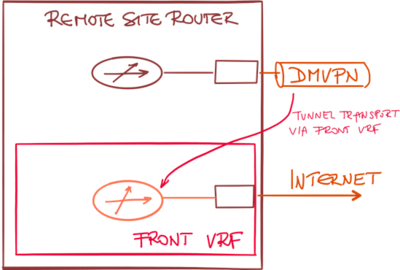
In these designs, a transport (front) VRF is created, and the WAN interfaces are placed in the transport VRF. This VRF has an independent routing table and default route, allowing the DMVPN traffic to use a different default route than the user-generated traffic.
A typical configuration using transport VRF is shown in the following figure:
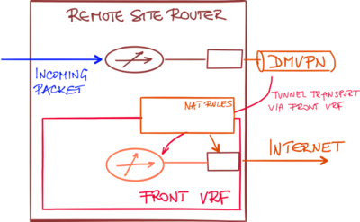
If you want to combine the front VRF designs with local Internet exit (and associated Network Address Translation – NAT), you have to implement inter-VRF NAT. Packets received through the global routing table (user traffic) have to be translated using NAT rules associated with an interface belonging to the transport VRF.
Configuring the NAT rules between the global routing table and transport VRF is not enough. There must be an entry in the global routing table (for example, a default route) that will send the incoming packet toward the Internet-facing interface.
With a route pointing to the Internet interface, the incoming packet might get forwarded to the upstream DMVPN tunnel (if the hub router announces a default route) or dropped.
There are two mechanisms that could be used to create the default route in the global routing table pointing to the Internet-facing interface in the transport VRF:
- Static default route in the global routing table pointing to the interface in the transport table;
- IP prefix export from VRF table into global routing table (available in IOS XE release 3.7S)
Once the default static route pointing to the Internet interface is present in the global routing table, the incoming packet could be sent toward the Internet interface creating a NAT translation entry on the way.
There’s no need to have a static route in the transport VRF to handle the return traffic.
The NAT translation entry created by the outgoing packet contains ingress and egress forwarding table information. When the return packet arrives, its (outside) destination IP address is in the transport VRF and thus routable to local interface which contains the NAT rules and associated NAT translation table.
When the destination IP address in the return packet is translated using the NAT translation entry that was created by the outgoing packet, the return packet is automatically forwarded using the correct forwarding table.
You can't leave comments on this web site, but you can add them to this blog post.


